Signed in as:
filler@godaddy.com

Performing the Risk Management Framework (RMF) process, particularly Steps 3 - 6 of the RMF involving scanning and remediation of vulnerabilities, directly to an operational system at the site, poses a risk of systemic damage and downtime for the operational systems. During the security hardening process, the operational system is not available to perform its intended mission. And some of the hardening scripts/commands are irreversible and can cause the operational system to be unusable if the incorrect scripts are executed.
Utilizing cybersecurity testbed to implement, test, and verify the security hardening reduces risk while maximining the operational availability of the system. Ideally, the cybersecurity testbed is a replica of an operational system, but it’s usually cost-prohibited due to the high price of the hardware setup. To minimize the hardware procurement cost, the cybersecurity testbed is not a replica of the operational system but consists of several Information Technology (IT) hardware representative of the essential functions performed by the system in normal use.
Technical Background
Department of Defense (DoD) Instruction 8510.01 released on March 12, 2014, established the DoD’s Risk Management Framework (RMF) for DoD Information Technology (IT). The RMF replaces the DoD Information Assurance Certification and Accreditations Process (DIACAP) and manages the life-cycle cybersecurity risk to DoD IT REF 1. It mandated all DoD IT, including Information Systems and Platform IT in support of research, development, and testing to obtain certification under the RMF process. A pictural diagram of the six steps of RMF is shown in Figure 1.
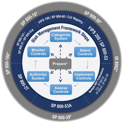
Figure 1: Six steps of the RMF process
REF: National Institute of Standards and Technology (NIST) U.S. Department of Commerce, https://csrc.nist.gov/Projects/Risk-Management/Risk-Management-Framework-(RMF)-Overview
The RMF includes six steps [REF]:
The six steps of the RMF, as described above, can be easily incorporated into the architecture of a new system being developed. Or the original developers of the system are still available to implement the required security hardening and risk mitigation process of the RMF. In most cases, the systems that are going through the RMF are older and are under the purview of operators/users with minimal support from the original system developer. The operators are then hesitant to perform the security hardening and risk mitigation of the RMF process due to technical deficiency on the system architecture. The technical issues involved the following:
As mandated by DoD, the operational system must obtain cybersecurity certification through the RMF process to have an Authorization to Operate (ATO) as DoD asset. Historically, test-range operational systems are incrementally upgraded over time. And each system installed is developed with the newest hardware technology and improved processing applications. Performing the first two steps (Categorization and Selection) can be done quickly performed because it only requires basic documentation of the system architecture. However, starting with Step 3 (Implementation of the security controls), which requires changes to the system architecture to meet compliance, posses a complicated scenario for the operator because of insufficient technical insight on the different system architecture that the original developer possessed.

Figure 1: Six steps of the RMF process

Figure 2: Simplified block diagram of a typical system
A simplified diagram of a typical system is shown in Figure 2. The IT on the typical system includes the signal generator, transmitter, receivers, recorders, processor/decoder, network switches, antenna control, and displays. Each IT must be independently scanned for vulnerabilities and remediated to meet cybersecurity compliance. All IT must have the latest version of security patches, including OS kernels and third-party maintenance updates.
Figure 2: Simplified block diagram of a typical system
Figure 3: Proposed centralized cybersecurity testbed
Technical Objectives
The objective is to design and build an unclassified offsite cybersecurity testbed for an operational system to test and verify security hardening and risk mitigation defined in the RMF. A block diagram of the proposed cybersecurity testbed is shown in Figure 3. The cybersecurity testbed is not a replica of an operational Telemetry system. But it consists of essential IT with telemetry-specific peripheral cards to represents the required services/functions performed by a telemetry system in a typical operation. To reduce the hardware procurement cost of the cybersecurity testbed, all non-intelligent subsystems are not part of the proposed system. Analog systems, such as local oscillators, amplifiers, filters, etc., are also not included. The overall cybersecurity testbed comprises of the following:
1. Nessus scanner
The Nessus scanner is a generic laptop that emulates the function of the ACAS’ Nessus scanner at the telemetry site. The Nessus scanner scans all the IT systems connected to the network. It will scan for open ports and enabled services that can be subjected to potential attacks.
2. Network switch
The network switch is a Cisco/Juniper switch that emulates the Local Area Network (LAN) configuration of all the IT. A cybersecurity compliant startup configuration is loaded in the switch to gauge its effect on the streaming telemetry data.
3. System/Environment Emulator
The emulator is a simple server or workstation that would generate input to the system IT. It checks connectivity between the system IT and also generate raw digital or analog data for the system to decode and process.
4. External Laptop
The laptop connects directly to the internet to download necessary security patches and policies, updated anti-virus definitions, and hardware and software maintenance updates from third-party developers. The laptop will serve the following functions:
5. System IT
The hardware that forms of the system IT is based on the current subsystem hardware. Generally, System IT is at least one server or workstation that defines the required IT needed to accomplish its day-to-day function. It would also include custom and specialized peripheral daughter cards that perform functions specific to data processing.
The server/workstation used in the System IT is based on the current model and capabilities of the compute nodes in the operational system. Selection of the server is based on the following specification:
The OS of the server is dictated by the current OS of the compute nodes in the operational Telemetry systems. The latest RHEL OS version with compatible hardware drivers is installed in the server for the Linux-based OS subsystem. The same applies for Windows-based OS and other OS’.
As shown in Figure 3, the cybersecurity testbed consists of two sections – one section includes a laptop that is connected directly to the internet, and one section is isolated in a LAN. The isolated LAN emulates the classified operational system that is not exposed to the external internet. Files downloaded from the laptop connected to the internet are transferred to the LAN via CD, DVD, and SSH. The LAN is not directly connected to the internet so that it would be protected from outside hackers/attackers. The cybersecurity testbed is situated in an unclassified environment where issues encountered during the testing can be openly discussed with other subject matter experts – i.e., manufacturer of the board and developer of the operational application.
The cybersecurity testbed will serve as the testbed for all the systems under going the RMF process. A logical block diagram of the cybersecurity testbed usage is shown in Figure 4. All the cybersecurity risk mitigation is first implemented in the testbed system drive, then rigorously verified by following a written testing procedure. Once verified, a clone of the system drive is installed at each of the sites.
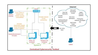
Figure 3: Proposed centralized cybersecurity testbed
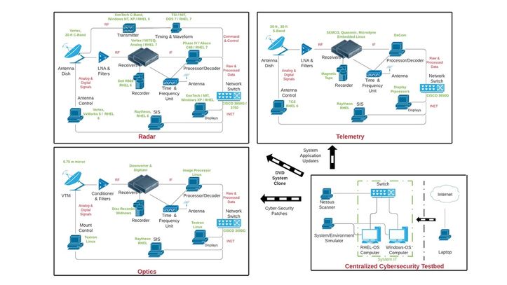
Figure 4: Block diagram of cybersecurity interconnect